UML class diagrams
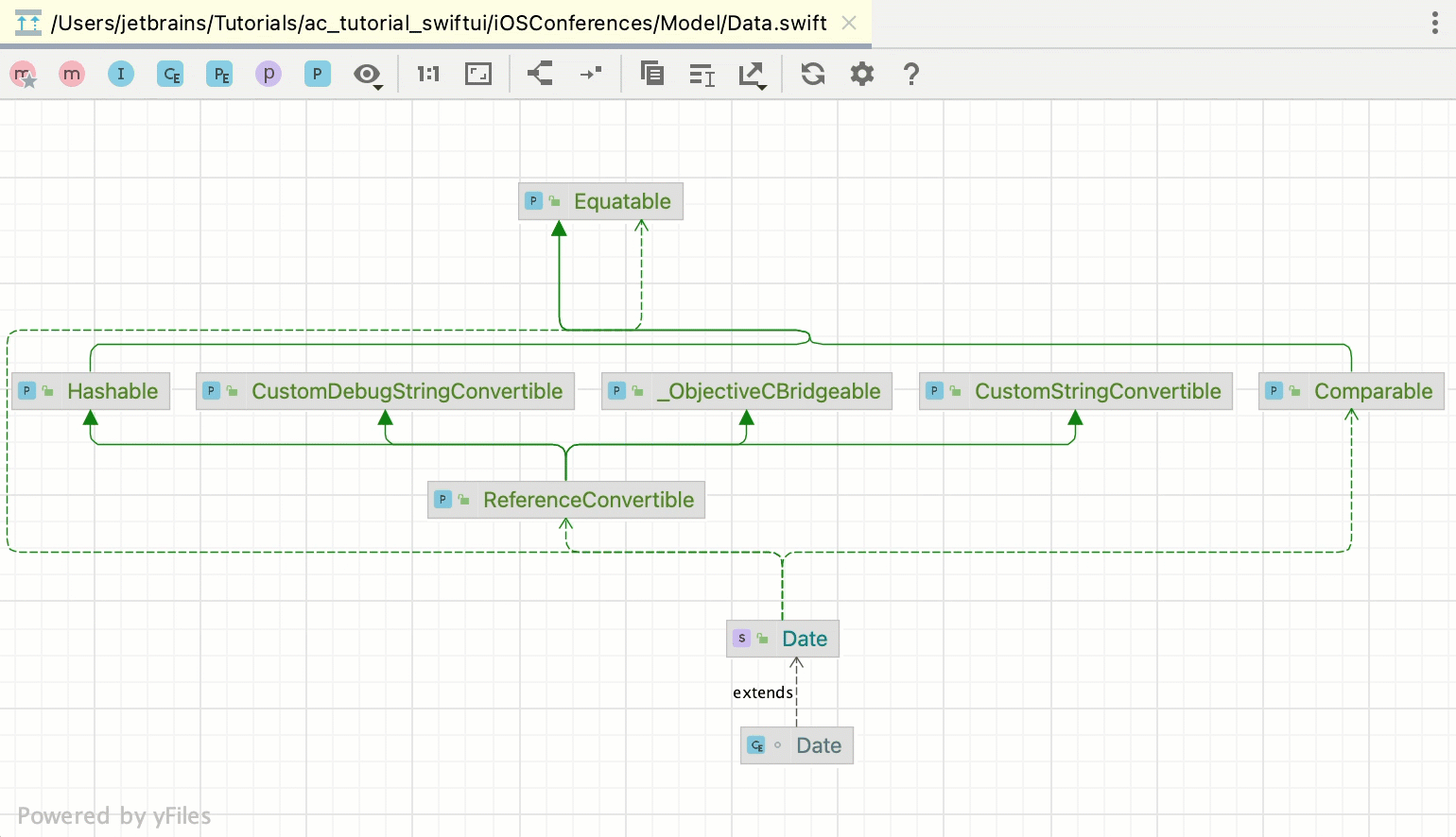
Last modified: 03 April 2023Right-click a class file or a package and select Diagrams | Show Diagram or Diagrams | Show Diagram Popup.
Enable the Diagrams plugin
This functionality relies on the Diagrams plugin, which is bundled and enabled in AppCode by default. If the relevant features aren't available, make sure that you didn't disable the plugin.
Press Ctrl+Alt+S to open the IDE settings and select Plugins.
Open the Installed tab, find the Diagrams plugin, and select the checkbox next to the plugin name.
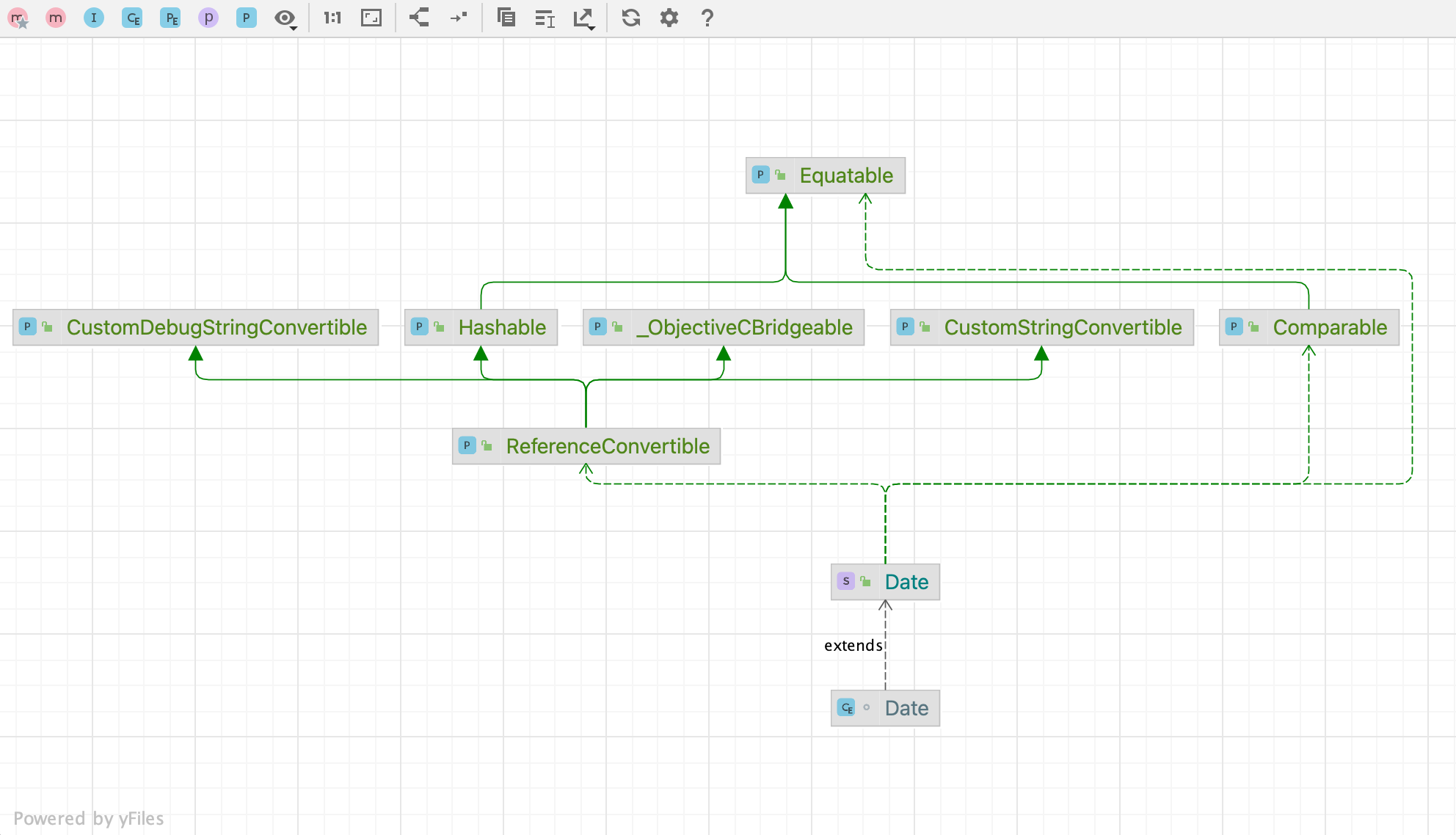
AppCode lets you generate UML diagrams for Objective-C and Swift. The diagrams help you analyze the structure of your application by showing types, their connections, methods, and fields.
View class diagram
In the Project tool window, right-click a file for which you want to create a diagram and select Diagrams | Show Diagram Ctrl+Alt+Shift+U or Diagrams | Show Diagram Popup (Ctrl+Alt+U).
In the editor, place the caret at the symbol that you want to show on a diagram and from the context menu, select Diagrams | Show Diagram.
You can use the UML Class diagram to evaluate how your local code changes affect the application.
From the context menu of the code editor, the Project tool window, or the Local Changes view, select Show Local Changes as UML, or press Ctrl+Alt+Shift+D.
The diagram opens in a popup. You can double-click a node to view changes in a Differences viewer.
To view changes in revisions as a UML Class diagram, in the History tab of the Version Control tool window, select the desired revision and select Show Diff as UML from the context menu or press Ctrl+Shift+D.
Navigation in UML diagrams
Find a diagram element
In the diagram editor, press Ctrl+F12.
In the list that opens, select an element you want to navigate to:
 Gif
Giftip
To quickly find an element in the list, start typing its name.
Show implementations
Select a type on the diagram.
Press Ctrl+Alt+B or select Show Implementations from the context menu:
 Gif
Gif
Jump to source code
Select a diagram element that you want to open in the code editor.
Press F4 or select Selected Element Actions | Jump to Source from the context menu:

Analyze class diagram
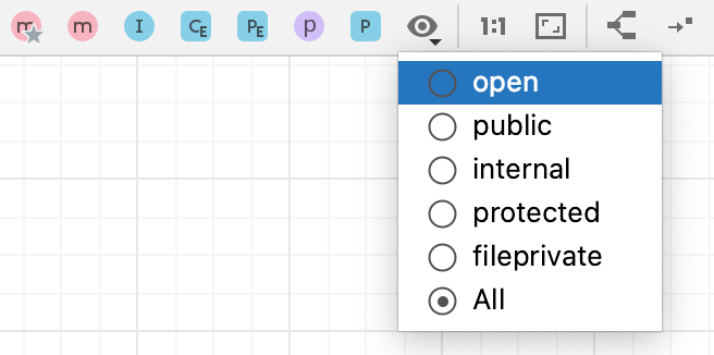
To see the list of methods, fields, and other code elements, select the appropriate icon on the diagram toolbar located on top of the diagram editor.

The lists are displayed based on the selected visibility level, which you can change.

To save the diagram as a file, right-click the diagram editor and from the context menu, select Export Diagram | Export to File and then the file extension in which you want to save the diagram.
Manage class diagram
When working with diagrams, use the context menu in the diagram editor to perform different tasks. You can view members of a type, delete types, see implementations, check parent types, and so on.
To select an element, click it in diagram.
To select multiple adjacent elements, keep Shift pressed and click the desired elements, or just drag a lasso around the elements to be selected.
To select multiple non-adjacent elements, keep Ctrl+Shift pressed and click the desired elements.
To select a class member, double-click the class element, and then use the arrow keys, or the mouse pointer.
Analyze graph
The Analyze Graph action group lets you analyze the graph in various ways such as perform auto clusterization, measure the node centrality, search cycles, filter path between two nodes, and so on.
Most of the time, generated diagrams are big and complicated. Typically, you want to concentrate only on the specific part of the diagram. AppCode lets you filter paths between two diagram elements.
In the diagram editor, select two nodes on which you want to focus and right-click one of them to open the context menu.
From the context menu, select Analyze Graph | Focus On Paths Between Two Nodes.
note
If you want to focus not only on just two nodes, but on how the selected node is connected with its neighbors, select the Focus on Node Neighborhood option from the context menu.
In the dialog that opens, select additional options if needed and click Find.

AppCode displays connections associated only with the selected nodes.

You can use this action to identify the important nodes in the graph.
In the diagram editor, right-click anywhere in the editor to open the context menu.
From the context menu, select Analyze Graph | Measure Centrality.
In the dialog that opens, select additional options if needed and click Measure.

The node "importance" is expressed via fractional value from 0.0 to 1.0 measurement and the brightest node selection should be explored first.

tip
Press Ctrl+Z to cancel the actions.
Productivity tips
- Enable the diagram preview
Open the Structure tool window Alt+7 and drag the shadow area to obtain the desired view. Select one or more nodes in the diagram to highlight the corresponding nodes in the preview area.
- Manage diagram layout
Right-click the diagram background, and choose Layout from the context menu. Then select the desired layout from the submenu. To apply the selected layout, click
on the diagram toolbar.
Alternatively, drag entities in the diagram manually to achieve the desired layout.
Thanks for your feedback!